What is a miter gear?
What is a miter gear?
A conventional miter gear pair is a bevel gear pair with equal tooth counts, a 1:1 ratio and shafts intersecting at 90 degrees. It redirects rotation without changing the nominal speed magnitude. Straight and spiral tooth forms are available. Equal tooth counts do not make arbitrary bevel gears interchangeable: the two gears must have compatible geometry and mounting requirements.
Separate the ratio from the shaft layout
A matched 20-tooth pair has a 1:1 ratio: an input speed of 600 rpm gives an output speed magnitude of 600 rpm. It does not provide the torque multiplication of a reduction stage, and real losses reduce transmitted power. A 20-tooth and 40-tooth bevel pair is a reduction pair, not a conventional miter pair.
Some catalogues also use the term angular miter for equal-ratio bevel pairs at other shaft angles. Specify the actual angle rather than relying on the name alone.

Specify the tooth form and the complete pair
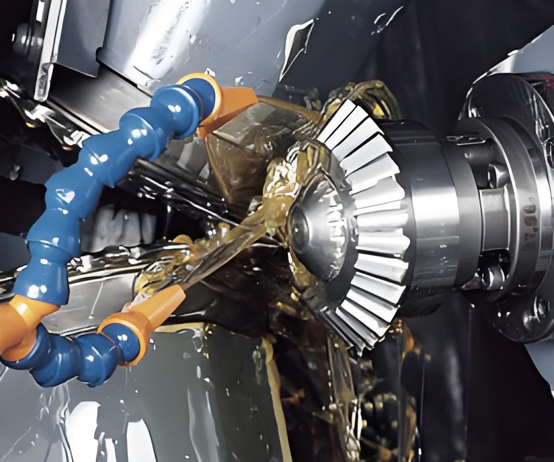
Straight miter gears have straight tooth traces; spiral miter gears have curved traces. The choice depends on duty, speed, noise targets and the complete bearing and housing arrangement. A spiral pair requires compatible hand and geometry; similar appearance or the same tooth count is insufficient.
The PairGears miter-gear guide explains the right-angle arrangement. Confirm material, heat treatment, face width, bore and shaft attachment on the pair drawings.
Check mounting even when the ratio is simple
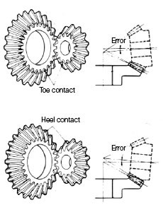
A 1:1 ratio does not remove assembly sensitivity. Verify shaft intersection, mounting distances, backlash and tooth contact pattern against the design. Shaft and housing deflection under load can change the contact location.
For a right-angle feed drive, first confirm that equal input and output speeds are actually required. Then assess torque, duty and lubrication. If speed reduction is needed, select a suitable reduction ratio instead of expecting a miter pair to supply it.