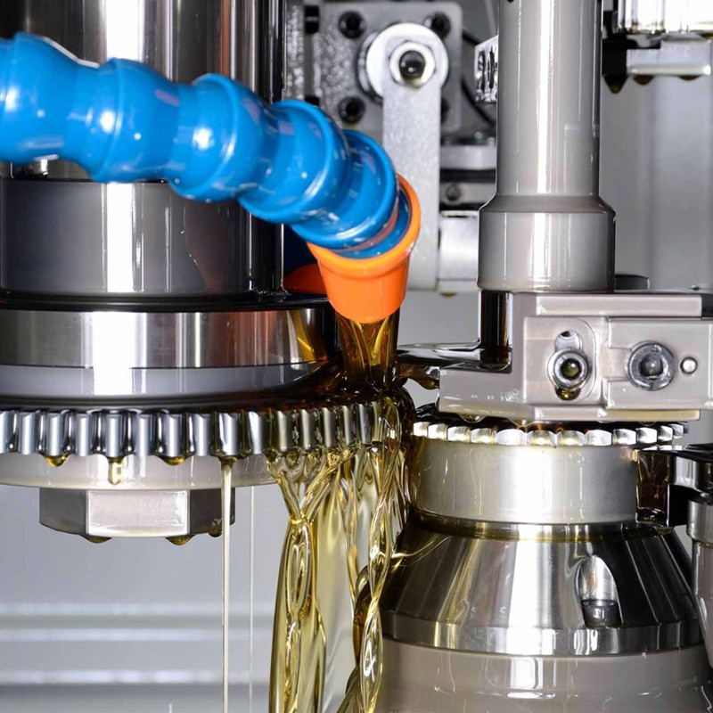
What is semi-topping on a gear tooth?
What is semi-topping on a gear tooth?
Semi-topping forms a chamfer at the edges of a gear tooth's top land, commonly through a specially shaped generating cutter. It removes the sharp tip corners while retaining the central top land. The feature helps limit burr formation and handling damage. Its size and position must suit the gear geometry; it is different from cutting the entire outside diameter or specifying functional tip relief.
Identify the tip feature on the drawing
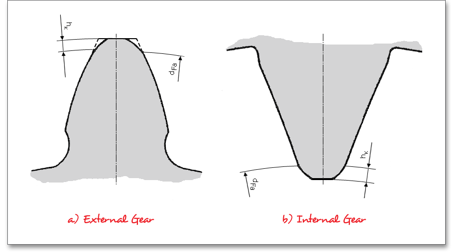
The chamfer lies where the tooth flank approaches the top land. State its required size and definition, such as the radial amount and the diameter where the full working profile ends. A general instruction to remove burrs does not define this geometry.
The illustration shows an addendum chamfer on external and internal teeth; it explains the finished feature, not a universal cutting method.
Distinguish semi-topping, topping and tip relief
- Semi-topping: generates the tooth-tip chamfer.
- Topping: also cuts the gear outside diameter during generation.
- Tip relief: modifies the working flank near the tip to manage engagement under load.
These cutter features serve different purposes. The PairGears gear-cutting guide provides the broader manufacturing context.
Check the cutter against the actual tooth geometry
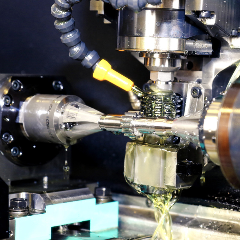
A modified cutter that produces the intended chamfer on one gear may produce the wrong feature on another tooth count or addendum. For example, a small pinion with a different profile shift should not automatically inherit a larger gear's semi-topping tool specification.
Provide the gear drawing, tooth count, module or DP, profile shift, tip diameter and chamfer target. Confirm the remaining active profile and the inspection method before accepting the proposed cutter.