
How is worm gear bending strength calculated?
Worm gear bending strength: calculate the working pair, not a ratio alone
Worm gear bending strength is checked from the working geometry, transmitted load and wheel tooth-root capacity, with factors for service, dynamics, load distribution, material and life. The result is only valid when the worm and wheel are modeled as one lubricated, thermally loaded pair. PairGears therefore needs real speed, torque, duty and layout data before a calculation can be interpreted.
Inputs that control the calculation
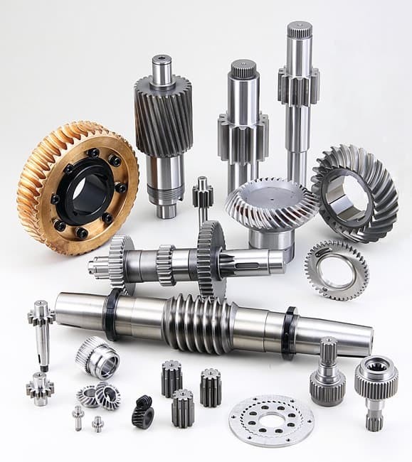
Define the pair and the duty: provide worm starts, wheel tooth count, module or pitch, lead angle, center distance, face width, materials, heat-treatment condition, input speed, output torque, load spectrum, required life, mounting arrangement and lubricant.
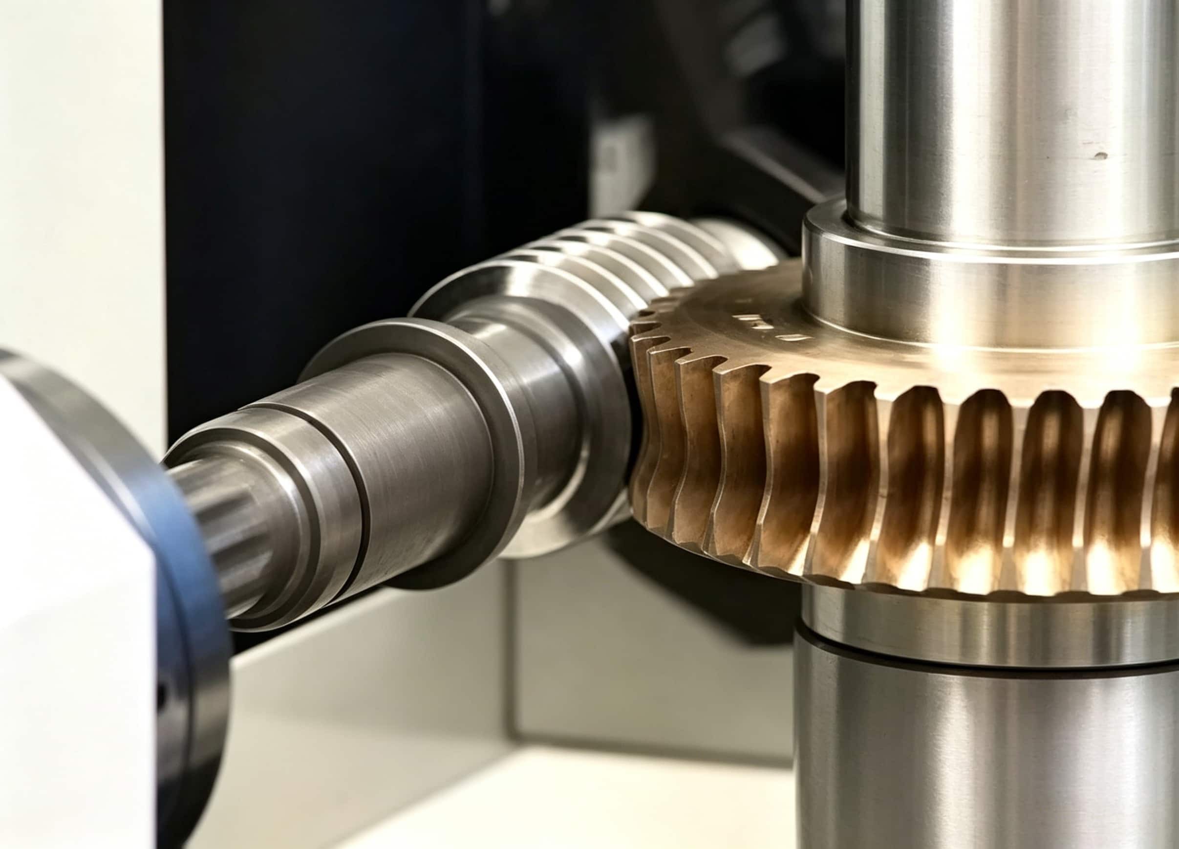
Calculate the transmitted forces from operating torque and geometry, then assess the wheel tooth-root stress against an allowable value that reflects its material and life. A recognized worm-gear method also checks wear, pitting, deflection and temperature; a bending pass alone does not establish service suitability. The PairGears worm-gear manufacturing guide lists the matched-pair data that should accompany a technical review.
Example and decision check
For the same output torque, changing wheel material, face width, lead angle or duty cycle changes the tooth-root demand and the allowable value. Record whether torque is continuous, intermittent or shock-loaded, and state the thermal and lubrication assumptions. Those conditions determine whether a calculated safety margin can be used for the actual gearbox.