
How can rack-and-pinion mesh interference be corrected?
Rack-and-pinion mesh interference: correct the cause, not just the clearance
Rack-and-pinion mesh interference is usually corrected by first separating a tooth-geometry or pitch mismatch from alignment, support stiffness or end-of-travel effects. Check the rack and pinion as a matched pair, then verify the mounting datum, center distance, tooth contact and backlash through the full travel. PairGears can review the drawing and duty conditions without assuming that one backlash setting fits every position.
Check the engagement path
Start with matching data: confirm module or DP, pressure angle, tooth form, helix direction where applicable, rack pitch and the specified operating center distance. Then inspect the pinion for runout and the rack for straightness, pitch consistency and mounting-face condition.
A tight spot at one location often points to eccentricity, local rack error, housing deflection or an end-zone geometry issue. Do not remove tooth material or add clearance before the contact pattern and the full stroke have been checked. The PairGears rack-and-pinion guide explains why pitch, runout, backlash and support rigidity have to be considered together.
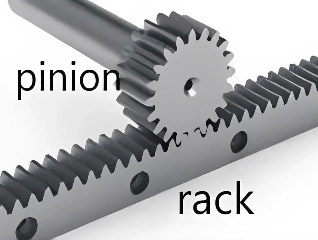
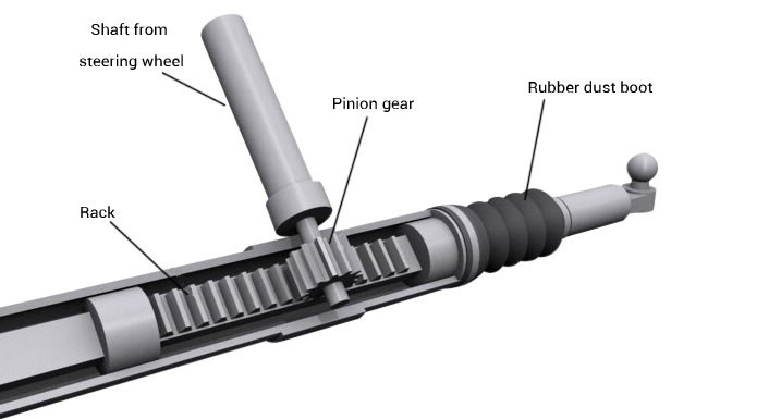
Example and decision check
If the mesh is smooth mid-stroke but tight near one end, measure rack straightness, end support and the pinion axis before changing nominal backlash. If the problem follows the same pinion angle, check pinion runout and tooth geometry. If it follows the same rack position, check rack pitch and mounting alignment.