
How should gear teeth and keyways be positioned?
Gear tooth and keyway positioning: use one datum scheme
Position gear teeth and keyways from one agreed datum—normally the bore axis plus a locating face. State whether the keyway is clocked to a tooth, a tooth space or a defined angular value, then inspect the bore, face, runout and angular relationship from that same reference. PairGears can review the drawing logic without assuming an unstated stock configuration.
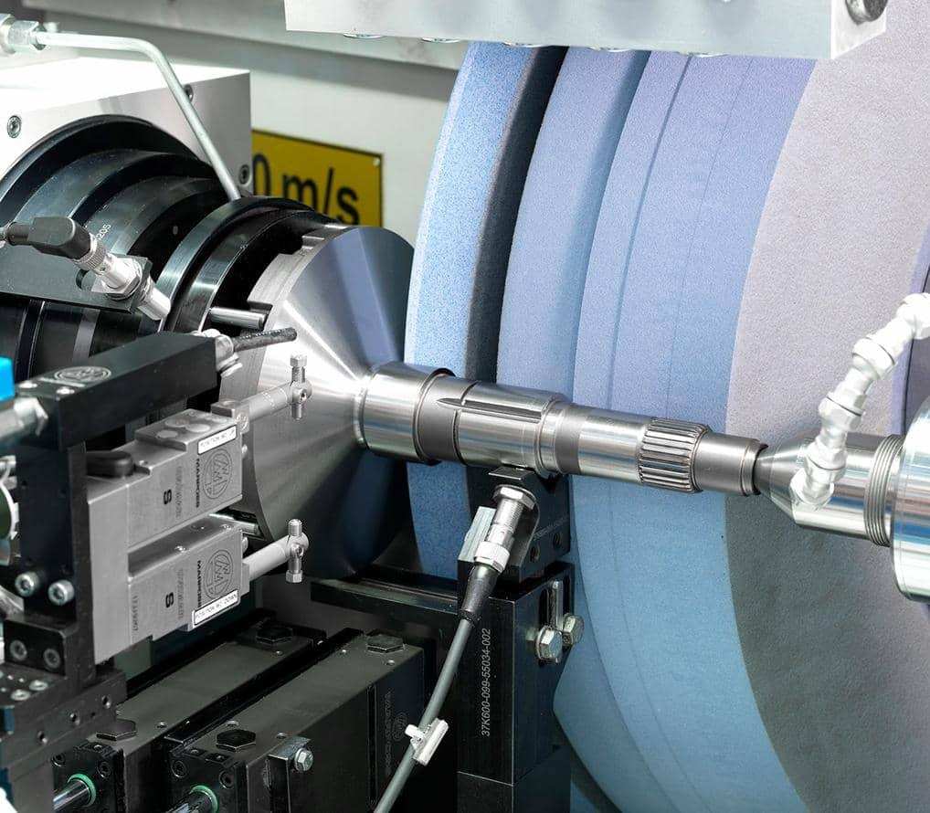
What to define before release
Define the reference before dimensioning: identify the bore axis, the axial locating face and the angular zero. Then specify the keyway width and depth, keyway standard, tooth or tooth-space reference, permitted angular deviation, bore fit and runout requirements. A note such as “keyway aligned to tooth” is incomplete unless it also defines which tooth feature and which measuring convention establish alignment.
Clocking matters when the driven part, sensor, timing mark, assembly fixture or mating feature has a fixed orientation. Use a controlled datum chain rather than accumulating dimensions around the circumference. The runout-verification FAQ explains why the mounting reference must be explicit.
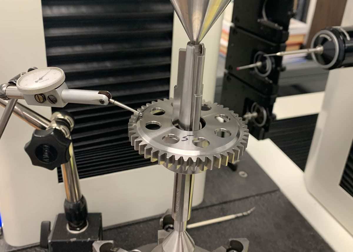
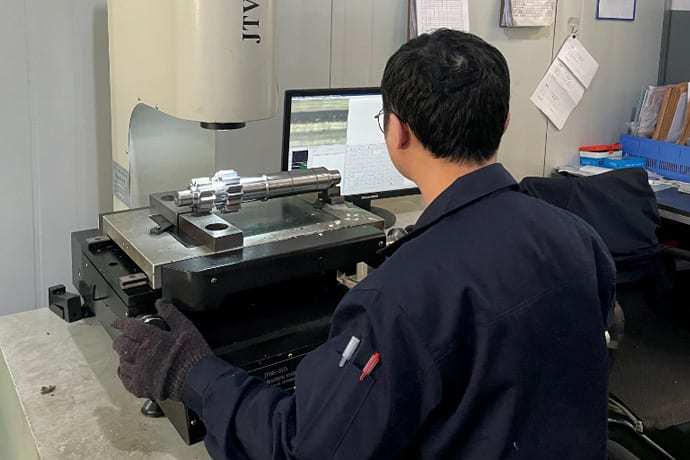
Example and decision check
If a keyway must sit at the center of a tooth space, state the angular position relative to the specified datum and how it will be measured. Inspection can then verify bore size and location, face runout, tooth runout and clocking separately; passing one of these checks does not prove the others.